01 · Structural Analysis

Front Suspension
Load Case Study

Illini EV Concept · Suspension & Brakes Lead · Aug 2024 to present

I ran both the knuckle and the lower control arm in SOLIDWORKS Simulation under two load regimes each, to see which part and which case actually sets the design. The result surprised me: the combined braking case carries only half the vertical load of a pure bump, yet it produces almost twice the stress. What governs this corner is longitudinal load, not how hard the wheel hits a bump.

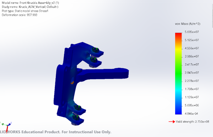
Knuckle under vertical bump, von Mises
FIG 1 · Knuckle, vertical bump. 56.2 MPa converged, FS 4.9.
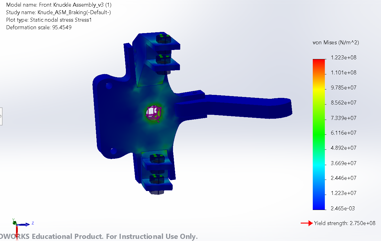
Knuckle under braking, von Mises
FIG 2 · Knuckle, braking + bump. 122.3 MPa, FS 2.2. The peak jumps to the wheel bearing bore.
Control arm under vertical bump with shock, von Mises
FIG 3 · Control arm, vertical bump with shock reaction. 106.0 MPa, FS 2.6.
Control arm under braking, von Mises
FIG 4 · Control arm, braking + bump. 195.8 MPa, FS 1.4. This is the case, and the part, that governs.
How the loads were built
Static basis225 kg ÷ 4 corners × 9.81 = 552 N per corner
Vertical bump3.0g, so 1,656 N
Braking + bump607 N longitudinal (1.1g) with 828 N vertical (1.5g), together
Cornering773 N lateral (1.4g). Defined, not yet run.
Material6061-T6 aluminum, yield 275 MPa
ConstraintsBolt connectors at UCA/LCA joints; bracket faces fixed
Target / toolFS 3.0 · SOLIDWORKS Simulation
Factor of safety vs. target
Control arm1.4
Target3.0
Knuckle4.9
Load case matrix
Component and casePeak von MisesFactor of safety
Knuckle, vertical bump56.2 MPa4.9
Knuckle, braking + bump122.3 MPa2.2
Control arm, vertical + shock106.0 MPa2.6
Control arm, braking + bump195.8 MPa1.4
What I took away
  • Longitudinal load governs, and it isn't close. The combined case puts 828 N through the corner vertically, half of the 1,656 N bump, plus 607 N fore-and-aft, and still drives peak stress up by 2.2× on the knuckle and 1.85× on the control arm. A braking force acts through a much longer moment arm about the suspension pickups than a vertical force does, so a smaller load does more damage. If I had sized these parts on bump alone, both would have been under-built.
  • When the load path moves, the critical spot moves with it. Under bump the knuckle is worst at its lower mounting boss; under braking the worst point shifts to the wheel bearing bore. There is no single danger zone to reinforce, which is exactly why every case has to be run rather than guessing at the ugliest one.
  • The control arm is what sets the corner. At FS 1.4 under combined bump and braking it sits below the 3.0 target and below every knuckle result, so that is where the redesign effort went, not into the part the team had been reworking.
  • The knuckle has margin to give back. Even in its worst case it holds FS 2.2, and peak deflection is only 0.018 mm, so it is both strong and stiff. That makes it a good candidate to shave mass from, which is worth more on an unsprung part than extra safety factor it doesn't need.
  • Where this stands. Cornering is defined at 1.4g but not yet run. I have verified mesh convergence on the knuckle (below); the control arm hasn't had that check yet, so I treat its FS 1.4 as a working number until it does.
01 · Verification

Mesh Convergence Study

Front knuckle · vertical bump case · SOLIDWORKS Simulation

The knuckle's peak stress lands at the lower control-arm mounting hole, a bolted and constrained feature, which is exactly where a fixed-constraint singularity would appear. A singular stress rises without bound as elements shrink, so the result is only reportable once the mesh has been shown not to be driving it.

Baseline mesh
FIG 5 · Baseline mesh. 11.3 mm global element size, 13,484 elements.
Refined mesh
FIG 6 · Refined mesh. 5.5 mm global with 1.5 mm local control at the peak region, 20,672 elements.
Peak locationLower control-arm mounting hole, unchanged under refinement
Max deflection0.018 mm at steering tie-arm tip
Reported value56.2 MPa · FS 4.9
Convergence data
MeshElementsPeak von Mises
Baseline, 11.3 mm13,48457.0 MPa
Refined, 5.5 mm + 1.5 mm local20,67256.2 MPa
Change+53%−1.4%
Why it holds
  • Refinement targeted the peak, not the whole part. Local control at 1.5 mm resolves the mounting-hole region while leaving the rest of the mesh coarse, a 53% element increase rather than several hundred percent.
  • The result moved 1.4% and its location did not move at all. A singularity grows with refinement and often migrates; a resolved stress converges and stays put. Both tests pass, so 56.2 MPa is a real, resolved stress.