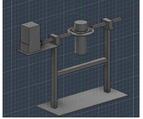
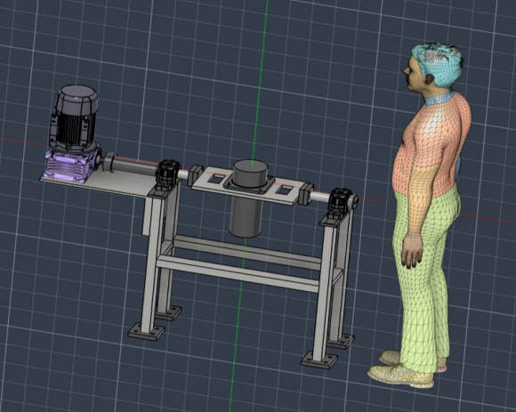
On the excavator assembly line a 40 kg hydraulic turning joint had to be rotated and held by hand while operators worked on it: slow, awkward, and hard on the people doing it. I designed a powered fixture that carries the joint, rotates it under a self-locking worm drive, and holds it at any orientation so no one has to muscle it around.
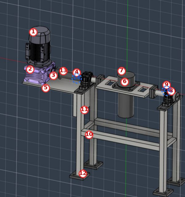
The entire fixture, in Fusion 360. I modeled the mounting plate the joint bolts to, the rotating shafts, the bearing-support integration, and the welded column-and-base frame, and I selected and integrated the full drivetrain (motor, worm gearbox, jaw coupling, bearings, locating plungers, and floor anchors), sizing everything to catalog parts so the design could be quoted and built.
| Part | 40 kg hydraulic turning joint |
|---|---|
| Requirement | 141 N·m at rotation axis |
| Delivered | 184 N·m, a 1.30× margin |
| Drive | Transtech TW63 worm gearbox + brake motor, jaw coupling; self-locking |
| Bearings | Spherical roller (SKF 22208) in SNL plummer-block housings, ×2 |
| Indexing | Halder locating plungers, ×4 |
| Frame | Welded mild steel: 12 mm plate, 60×40×4.5 mm pipe columns, Hilti floor anchors |
| Software | Fusion 360 |
The first concept looked quite different from what I ended up with. Three changes drove the design to its final form: one came from a manager review, two from rechecking my own numbers.